Graphics programming on Acorn Archimedes / RISC OS with ARM assembly
Contents
- Introduction
- API Introduction
- 1) Display modes (256 colors) and VDU setup
- 2) Multiple screen banks, switching banks and updating screen address
- 3) Getting the screen address and drawing
- 4) Clearing the screen
- 5) Waiting for VBL, polling keyboard
- 6) Printing characters and values
- 7) Using timers (computing / displaying FPS)
- 8) 16 colors mode / palette setup
- 9) 16M colors mode (True Color)
- Aside : Default 256 colors palette generator
- Aside : Files
- Aside : Playing simple sounds
Introduction
This article is a small introduction to the world of
low-level graphics code on RISC OS.
It is strongly targeting Acorn Archimedes hardware (especially 256 colors mode)
but is also compatible with later hardware such as RISC PC
or Raspberry PI
running RISC OS 5.
It focus on low-level graphics programming, 256 colors mode
(so Archimedes era up to now compatibility) and also 16M /
16 colors mode, it make uses of few RISC OS system calls for video
setup.
Here is what the article talk about:
- display modes (16 colors, 256 colors and 16M + modern display
mode) and text cursor setup
- multiple screen banks setup (for double or triple buffering), switching banks
- getting the screen address and drawing stuff
- clearing the screen
- waiting for VBL, polling keyboard
- printing characters / values
- using timers, computing / displaying FPS
- 16 colors mode / palette setup
- 16M colors mode (24-bit True Color)
The main goal is to let you have full control over the
frame-buffer (the only way to get the most of the hardware !)
with a clean graphics setup so you can do any graphics like games,
demos, effects on your own, it will just boil down to writing / be
proficient at ARM assembly code.
The side goal is to provide some hints at how to code graphics
stuff on RISC OS and Archimedes with many links.
The code in this article is the accumulated knowledge (with
help of the Stardot
community) of when i started graphics programming on the
Archimedes. It ended up into a personal library which can be found
here.
The code use the
BBC BASIC assembler syntax so can be used directly in BBC
BASIC.
Requirements
The code here run as-is on a stock Acorn Archimedes (and later
hardware!) and does not need external programs. To start doing
graphics programming on this platform you just have
to:
- use an emulator like Arculator or a Raspberry
PI running RISC OS 5 (or any platforms supporting RISC
OS)
- use !Edit
(bundled text editor) or a modern equivalent (like StrongEd or
Zap)
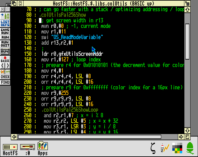
- use an assembler (or just use the RISC OS bundled BBC BASIC and its inline assembly which is what i use here!), you can also use my BBC BASIC assembly tool which is easy to use
For old RISC OS versions i recommend Zap (1.40 run
on RISC OS 3) as code editor, it support syntax highlighting, line
numbers and many features.
For recent RISC OS versions i recommend StrongEd which is
bundled on Raspberry PI, the cool thing about StrongEd is that it
comes with all the documentation you need to program on RISC OS in
the form of StrongHelp which is basically a tightly integrated
manuals browsing program, all RISC OS API down to ARM assembly
documentation is available this way!
StrongEd also has a hex editor and a disassembler just like
Zap.
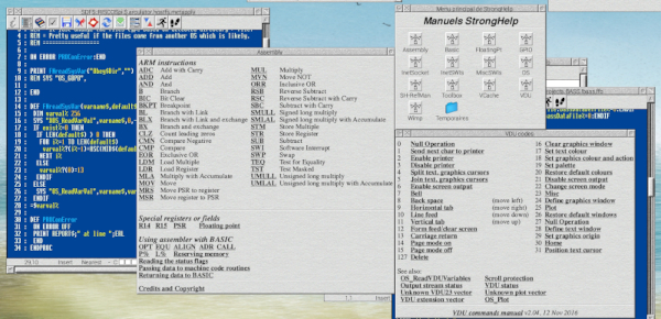
StrongEd code editor with StrongHelp; a strong
combination!
Have a look at the Archimedes
archive for more applications.
Zap code editor running on RISC OS
3
Zap is actually more than a code editor and
has extras like a hex editor and a disassembler !
Unpacking archives on RISC
OS
If you want to use Zap you will have to download a ZIP file
which must be unpacked in RISC OS to keep the files metadata
(files type), SparkPlug
extractor can be used for that on old RISC OS versions which
does not support this out of the box. SparkPlug can also be found
here.
What about BBC BASIC ?
This article focus on doing it all in assembly but you can do
most of the things below with some easier
BBC BASIC calls and only switch to assembly for performance
critical parts, this is perhaps the most friendly way to code on
Archimedes. The BBC BASIC manual can be found
here. (also include the inline assembler
documentation)
Want to code in C ?
RISC CPU are friendly to efficient code generation so C can
also be a great (and less of a hassle) alternative, C compilers for
early Archimedes are available here for a mid 90
version or here for a late 80s
version.
Here is an
example with sources of a small fixed-point 3D mesh renderer
for Acorn Archimedes written in C89 and ARM assembly.
ArchieSDK is
also friendly.
API Introduction
You may want to read about how to communicate with RISC OS API
if you are new, two of the most important system calls (you will
encounter these often for settings things up) are OS_Byte
and OS_WriteC
and its variant.
You may also want to look at the original ARM2 documentation
which is still valid for ARM3.
Compatibility notes
- if you want program compatibility from ARM2
(Archimedes) to Raspberry PI (and modern hardware) you must take
caution of some small ARM differences (like the usage of movs which will be not compatible as-is on modern platforms
unless the ARM code is in Thumb
mode), in any cases it should work okay if you stay with
straightforward ARM2 instructions. You must also take caution on
display modes, some may not be available / compatible.
- if you don't use BBC BASIC assembler you may have to define symbols like OS_WriteC and OS_Byte to their corresponding RISC OS constant
- if you go with a mode which support more colors (eg. 16M colors) you may have to change how you handle the frame-buffer and adapt some of the code below (screen clearing etc.), same if you go to lower colors modes, see the 16 colors mode and 16M colors mode for example.
- 256 colors mode code will generally works on modern RISC OS but old screen modes might not work with your monitor or work differently, refer to the old screen modes table for details
- On platforms with a GPU (modern platforms) the bank switching must be done before the VBL wait for less tearing. So it will typically be : update back buffer, switch screen banks and wait for VSync.
- the VIDC can be programmed directly, see the
datasheet, this will break compatibility though
Note for VGA type screen mode : on early hardware
(prior A3010) the detection of the monitor type is not available so
you may get a different screen mode than the one which works on
says A3010 even though it is compatible so you must take care of
configuring your monitor type in RISC OS for these screen
modes, this thing confused me a lot in the emulator because the
high res mode i requested (640x480 1 bpp) which worked on A5000
didn't work as expected on early machines even though the machine
monitor was set to "VGA" in the emulator.
Things to know
The frame-buffer in 256 colors mode (and below) is just a
linear series of 8-bit values which represent the palette index, to
draw stuff you just poke at the screen address + an offset which
represent the position as computed by
x + y *
screenWidth
. Lower colors modes may be interesting to speed
things up and use less memory. (writing a word = 8px at once for
example in 16 colors modes instead of 4px in 256 colors mode)On Raspberry PI the frame-buffer in 16M colors mode (24-bit
True Color) is a linear series of 24-bit values in RGB888
format.
The main graphics API for RISC OS is the VDU driver, which is
provided by the kernel. Commands are invoked by sending special
character codes to the VDU stream. (using SWI like eg.
OS_WriteC or OS_WriteI)You can learn more about what is possible with the VDU
here.
The RISC OS graphics API has a lot of content and provide an
easy way to do graphics right away (like drawing shapes), it is
however slower than custom code and we will mainly use it as a way
to produce our own low-level graphics code here. You are however
free to mix OS calls and your own graphics code which can become
handy for non time critical stuff.
On the first Archimedes (A3xx) there is about 160000 cycles
available between VBL. (interlaced, it is about 300 less without
interlacing)
Video / sound may steal some of those cycles
(and memory refresh outside active display) so there is a bit less
available in reality.
To quit your program properly a call to OS_Exit
must be made at the end of your program.
1) Display modes (256 colors) and VDU setup
- only enable OS_WriteC (and others) VDU output through OS_Byte 3 (disable printer / serial driver since we will not use them, we will use the VDU output a lot however)
- setup 256 colors 320x256
display mode with VDU
code 22 (switching mode is as easy as changing 13 to another
constant like 9 for 16 colors mode 320x256)
- disable blinking text cursor with
OS_RemoveCursors (can also be disabled with VDU
code 23,1)
; 1.

mov r0,#3

mov r1,#84

swi "OS_Byte"


; 2.

mov r0,#22

swi "OS_WriteC"

mov r0,#13

swi "OS_WriteC"


; 3.

swi "OS_RemoveCursors"
OS_WriteI
which write an immediate byte may replace MOV + OS_WriteC (compact
code), here is an example which replace the second step of the code
above :
swi &116 ; 22

swi &10D ; 13
Note :
OS_ScreenMode 0 (RISC OS 3.5+ so RISC PC era) can also be
used to setup the display with more parameters such as mode
flags to directly setup a greyscale palette (RISC OS
5.21+)
2) Multiple screen banks, switching banks and updating screen address
This part is optional if you don't need double
buffering / more screen memory. Switching display mode will
always allocate enough screen memory for the selected mode.
'Banks' are just some allocated space in memory that can be
switched easily and quickly through the bank
switching method.
If you need multiple screen banks you must allocate twice or
more the amount of screen memory, this part show how to do that
easily for any number of banks needed.
- get current mode (320x256) screen size with OS_ReadModeVariable where 7 is querying the OS for "Number of bytes for entire screen display"
- compute the total amount of bytes to hold all the banks (here 2 for double buffering, 3 for triple etc.)
- get current number of bytes allocated for the screen area with OS_ReadDynamicArea
- increase screen area size (relative to current) with
OS_ChangeDynamicArea so that it fit our banks
Note: you may wonder why we have to do the 3 / 4 step
in order to allocate (instead of just allocating right away), the
reason is mostly because OS API only support relative + -
allocation. (probably due to backward compatibility with Arthur OS
?)
; 1.

mvn r0,#0

mov r1,#7

swi "OS_ReadModeVariable"


; 2

mov r3,#2 ; number of banks

mul r1,r2,r3

mov r2,r1


; 3

mov r0,#2

swi "OS_ReadDynamicArea"


; 4

sub r1,r2,r1

mov r0,#2

swi "OS_ChangeDynamicArea"
Why you may need more banks (others than multiple buffering)
More screen memory (banks) may become handy if you have
drawing code that get outside the bottom area. Your program may
crash without more screen memory. Having more let your graphics to
go onto the other screen once it reach the bottom so by clever
usage of banks you may allow top/bottom overflow and it may be
handy for debugging / optimization or special effects.
Switching banks
Once enough memory is allocated for the screen banks you can
switch the visible bank with OS_Byte
113 and you can redirect all VDU drivers calls to another bank
with OS_Byte
112. For double buffering you need to do that once per loop:
one bank is displayed while the other bank is written and then you
flip them once done.
Here is a routine that switch between two screen banks in the
case of double buffering (as setup above):
.gfxUtilsCurrentScreenBank

  dcd 1

.gfxUtilsSwitchScreenBank

  ; select the visible screen bank

  mov r0,#113

  ldr r1,gfxUtilsCurrentScreenBank

  swi "OS_Byte"


  ; increase current bank by one, if over 2 go back to the
first bank

  ldr r1,gfxUtilsCurrentScreenBank

  add r1,r1,#1

  cmp r1,#2

  ble gfxUtilsDoNotResetBank

  mov r1,#1

  .gfxUtilsDoNotResetBank

  str r1,gfxUtilsCurrentScreenBank


  ; select the VDU/draw bank

  mov r0,#112

  swi "OS_Byte"

 mov r15,r14
This routine is flexible enough for triple buffering with
little changes.
Shortcut way to
allocate screen banks
Since switching mode always allocate enough screen memory for
the mode you can use this behavior to let it allocate banks without
a call to
OS_ChangeDynamicArea by switching to a higher mode prior your
mode, this may prove useful for code golfing stuff because
switching mode can be done in two instructions. eg: switch to mode
15 (640x256 256 colors) then mode 13 (320x256 256 colors) to get a
double screen memory (so two banks) for your mode 13
setup.
Once the VDU/draw bank is switched you will need to get the
current screen address to start drawing stuff.
3) Getting the
screen address and drawing
This part deal with getting the screen address so we can start
drawing stuff by writing some bytes !
Getting the current screen address can be done with
OS_ReadVduVariables with VDU variable 148 as parameter:
; parameters for
OS_ReadVduVariables

.gfxUtilsScreenAddrInput

 dcd 148

 dcd -1

; this will contain the current screen address once
gfxUtilsUpdateScreenAddr is called

; you can access this at any times after an update with eg. ldr
r0,gfxUtilsScreenAddr

.gfxUtilsScreenAddr

 dcd 0


.gfxUtilsUpdateScreenAddr

  adr r0,gfxUtilsScreenAddrInput

  adr r1,gfxUtilsScreenAddr

  swi "OS_ReadVduVariables"

 mov r15,r14
Calling gfxUtilsUpdateScreenAddr will put the
screen address at the location pointed by gfxUtilsScreenAddr label.
If you use a single screen bank you just call
gfxUtilsUpdateScreenAddr once before your main loop.
For multiple banks you will need to call it every times you
switch banks so you get the current VDU/draw bank screen address at
the location pointed by gfxUtilsScreenAddr
label.
Once called changing pixels color is as easy as writing bytes
(or words) to the screen address + adding some offset:
ldr r0,gfxUtilsScreenAddr ; get screen
address (after gfxUtilsUpdateScreenAddr is called)

add r0,r0,#120 ; pixel position as computed by x + y *
screenWidth

mov r1,#128 ; some palette index which will be the color of the
pixel

strb r1,[r0] ; plot
It may be useful to get the screen size (in bytes) as well
which can be done with
OS_ReadModeVariable :
; this will contain the current
screen size (in bytes) once gfxUtilsUpdateScreenSize is called

; you can access this at any times after an update with eg. ldr
r0,gfxUtilsScreenSize

.gfxUtilsScreenSize

 dcd 0


.gfxUtilsUpdateScreenSize

 mvn r0,#0

 mov r1,#7 ; get screen size

 swi "OS_ReadModeVariable"

 str r2,gfxUtilsScreenSize

mov r15,r14
4) Clearing the screen
Clearing the screen can probably be done with OS calls
(VDU 12
or VDU
16 seems a good start) eg: a short and easy way to clear the
graphics window (VDU 16) :
swi OS_WriteI+16
The following code show how to clear the screen
manually.
The straightforward version use a loop with
strb instruction, it is kinda slow:; r0 = offset to add to current screen
address (start position, 0 = top left)
; r1 = screen size (in bytes, so like 320*256)
; r2 = color (palette index)
.gfxUtilsClearScreen
ldr r3,gfxUtilsScreenAddr
add r0,r3,r0
.gfxUtilsClearScreenLoop
strb r2,[r0],#1
subs r1,r1,#1
bne gfxUtilsClearScreenLoop
mov r15,r14The routine above is just like a memset, the parameters are
just the offset at which you want to start clearing the screen, the
amount of pixels to clear and the color (palette index).
The clear screen routine below use ARM block copy instructions
which is probably the fastest method to clear the screen, clearing
40 pixels at a time:
; r0 = offset to add to current screen
address (start position, 0 = top left)

; r1 = 40px based length, in 320x256 mode a full-screen clear is
(320*256 / 40)

; r2 = color (palette index)

.gfxUtilsClearScreen

  ; get screen address in r3, see "Getting the screen address"
above

  ldr r3,gfxUtilsScreenAddr

  ; add offset (so you can start clearing at a specific
position)

  add r0,r3,r0


  ; propagate clearing color to all the bytes (4px per
register)

  orr r2,r2,r2, LSL #8

  orr r2,r2,r2, LSL #16


  ; prepare 40px block

  mov r2,r2:mov r3,r2:mov r4,r2:mov r5,r2

  mov r6,r2:mov r7,r2:mov r8,r2:mov r9,r2:mov r10,r2

  mov r11,r2

  ; clear screen 40px at a time

  .clearScreen

   stmia r0!,{r2-r11}

   subs r1,r1,#1

  bne clearScreen

 mov r15,r14
This routine handle all screen resolution if it is
divisible by 40. (most screen mode on Archimedes)
The routine can be adjusted to clear even more pixels
at once (up to 52) by using the remaining registers (r12, r13, r14)
where r14 (which will contain the routine return address) must be
stored prior the screen clearing and restored after. The only
downside is that you may write outside screen boundary if your
number of pixels is not divisible by 52. This is why i settled with
40 pixels block on the routine above as it can handle most of the
Archimedes modes.
A routine which handle the overflow is possible and
not necessarily complex but is a bit too long to show
here.
The fastest version on ARM2 (56px at once) can be
done by unrolling the loop at the price of dense code. This may be
slower on ARM3 due to the cache.
In 16 colors mode 112px can be cleared at once
etc.!
5) Waiting for VBL, polling keyboard
VSYNC
For smooth visuals with no tearing you may want
Vertical synchronization. This can be done easily with OS call
OS_Byte
19 which will wait until the beam reach the bottom of the
screen, then you are free to draw stuff if you use a single bank or
switch banks.
Checking for pressed
keys
6) Printing characters
and values
mov r0,#19

swi "OS_Byte"
Checking for pressed
keys
You may want to poll the keyboard for pressed keys. This is
done by scanning for a particular key with OS_Byte
129:
; check if a key is pressed

; Z = 1 if pressed

; r0 = keycode

.sysUtilsIsKeyPressed

  eor r1,r0,#&FF

  mov r0,#129

  mov r2,#255

  swi "OS_Byte"

  cmp r1,#255 ; &FF if pressed 0 otherwise

 mov r15,r14
This scan for a single key but OS_Byte 129 can also do more
(scan a range or scan with a time limit), keycodes can be found
here.
Quick check for escape key
OS_ReadEscapeState SWI can be used to check escape key state as
a single instruction.
.loop

 swi "OS_ReadEscapeState" ; check key state (will set C
flag)

bcc loop ; loop unless C flag is set (ESCAPE key is
pressed)
6) Printing characters
and values
Characters output with the text cursor (some sort of text mode
API) is a flexible way to draw characters easily (for debugging,
text-adventure games etc.), the API support a wide range of
controls for things like linefeed, text position etc. you can also
customize the way it is rendered.
Printing text can be done easily with OS call OS_WriteS:
swi "OS_WriteS"

 equs "Hello World!" ; any strings

 dcb 0 ; must always end by a null byte

 align ; keep things word aligned
RISC OS API also provide a way to format values (see any
OS_Convert* OS call in the
SWI list, also OS_BinaryToDecimal when
null char. isn't needed) which may be extremely convenient for
debugging and games:
.sysUtilsPrintInteger

 adr r1,vIntegerToPrint

 mov r2,#12

 swi "OS_ConvertInteger4"

 swi "OS_WriteS"

 .vIntegerToPrint

  dcd 0

  dcd 0

  dcd 0

 mov r15,r14
Calling sysUtilsPrintInteger will print the
value in r0.
To control the text cursor position and appearance see text
cursor
VDU calls.
7) Using timers (computing / displaying FPS)
Timers are necessary for a wide range of things:
- bench-marking your code / monitoring frame rate
- maintaining the same animation speed when your code run on a 1987 8MHz CPU and when it run on a faster CPU
RISC OS provide a centiseconds resolution timer with OS call
OS_ReadMonotonicTime.
Here is an example of a centiseconds counter as a set of
routines:
; start a simple centi-seconds timer

.sysUtilsStartTimer

  swi "OS_ReadMonotonicTime"

  str r0,sysUtilsTimerAddr

  mov r15,r14


; will hold start time

.sysUtilsTimerAddr

  dcd 0


; stop timer

; r0 = centiseconds elapsed between start / stop call

.sysUtilsStopTimer

  swi "OS_ReadMonotonicTime"

  ldr r1,sysUtilsTimerAddr

  sub r0,r0,r1

  str r0,sysUtilsTimerAddr

 mov r15,r14
Call sysUtilsStartTimer then later
sysUtilsStopTimer and you will get the elapsed time
(centiseconds) between both calls in r0.
There is some ways to have higher resolution timers (as used
by RasterMan
which provide HSYNC / raster line interrupt on Acorn Archimedes,
something difficult to do as it require very high precision timer)
but it is out of scope, centiseconds resolution should be
sufficient for many things.
Frame rate
The frames per second can be computed / displayed with this
set of routines:
; initialize FPS timer

; r0 = modified

.sysUtilsInitFPSTimer

 swi "OS_ReadMonotonicTime"

 str r0,sysUtilsFPSTimer

 mov r15,r14


.sysUtilsFPSTimer

 dcd 0

.sysUtilsFPSFrame

 dcd 0

.sysUtilsFPS

 dcd 0


; compute FPS

; r0,r1 = modified

.sysUtilsComputeFPS

 swi "OS_ReadMonotonicTime"

 ldr r1,sysUtilsFPSTimer

 sub r0,r0,r1

 cmp r0,#100

 ble sysUtilsFPSIncFrame

   ldr r0,sysUtilsFPSFrame

   str r0,sysUtilsFPS

   mov r0,#0

   str r0,sysUtilsFPSFrame

   swi "OS_ReadMonotonicTime"

   str r0,sysUtilsFPSTimer

  mov r15,r14

 .sysUtilsFPSIncFrame

  ldr r0,sysUtilsFPSFrame

  add r0,r0,#1

  str r0,sysUtilsFPSFrame

 mov r15,r14


; print FPS

; r0,r1,r2,r13 = modified

.sysUtilsPrettyPrintFPS

 swi "OS_WriteS"

  equs "FPS: "

  dcb 0

  align

.sysUtilsPrintFPS

 ldr r0,sysUtilsFPS

 mov r13,r14

 bl sysUtilsPrintInteger

 mov r15,r13
Call sysUtilsInitFPSTimer before your main
loop then call sysUtilsComputeFPS /
sysUtilsPrintFPS at the end of your main loop.
You may have to call VDU 30 to move the text cursor to its 'home'
position after printing the value. VDU 13 which only reset the X
position of the text cursor also works.
Note: OS_Word
can also be used for its interval timer / system clock which are
readable and writable, this may be more convenient to
use.
8) 16 colors mode / palette setup
16 colors mode may be interesting to speed things up and use
less memory.
The main difference between 16 / 256 colors mode is that a
byte (so a pixel in 256 colors mode) hold two pixels in 16 colors
mode, each 4-bit data represent the palette index so you can
actually change 8 pixels at a time if you write a word value.
Note that it take 2x less memory than the 256 colors mode, for
screen coordinates you may have to divide by two since a byte is
actually two pixels.
The code below remain relevant for low colors modes after some
small changes.
Palette setup
Palette setup can be done with VDU
19 mode 16, the routine below take an address in r0 where a
whole palette (so 16 x R,G,B values) is stored as a series of 3
bytes value. Note that to pick from the 4096 possible colors each
colors byte must go by increment of 16, this give a total of 16
possible values for each color components.
 ; 16 colors dummy VDU 19 command pal
data which will get modified by the routine below

 .gfxUtilsPalData

  dcb 19

  dcb 0 ; palette index

  dcb 16

  dcb 0 ; r

  dcb 0 ; g

  dcb 0 ; b

  align

 ; = setup 16 colors palette

 ; r0 = palette data address (serie of bytes which represent
red,green,blue for 16 colors)

 .gfxUtilsSetupPalette16

  mov r3,r0

  adr r0,gfxUtilsPalData

  mov r1,#6

  mov r2,#0

  .gfxUtilsSetupPalette16Loop

   ldrb r4,[r3],#1

   strb r4,[r0,#3]

   ldrb r4,[r3],#1

   strb r4,[r0,#4]

   ldrb r4,[r3],#1

   strb r4,[r0,#5]

   strb r2,[r0,#1]

   swi "OS_WriteN"


   add r2,r2,#1

   cmp r2,#16

   bne gfxUtilsSetupPalette16Loop

  mov r15,r14
Notes
- OS_Word 12 can also be used to setup the palette, it may be faster than the routine above, easier and a bit more flexible.
- VDU 19 specific modes can be useful to also change the border
and cursor colors, you can also define some colors to flash by
changing the flashing palettes individually (it swap between two
palette at regular interval) which may be useful in some games, VDU
19 mode 16 actually set both flashing palette so you don't see any
flashing colors and it act like a normal palette.
Clearing the screen
Here is a screen clearing routine similar to the 256 colors
mode except that we pack the palette index from r0 into all 4-bit
group of r0 so the
strb instruction actually
change two pixels value at a time. ; r0 = color (palette index)
; r1 = offset to add (in bytes)
; r2 = screen size (in bytes)
.gfxUtilsClearScreen16
orr r0,r0,r0, LSL #4
ldr r3,gfxUtilsScreenAddr
add r1,r3,r1
.gfxUtilsClearScreenLoop
strb r0,[r1],#1
subs r2,r2,#1
bne gfxUtilsClearScreenLoop
mov r15,r14
Drawing
Since a byte contain 2 pixels the pixel drawing routine must
only change 4 bits of a byte compared to the 256 colors mode (you
may also need to combine what is on screen as well so you don't
update other pixels) :
ldr r0,gfxUtilsScreenAddr ; get
screen address (after gfxUtilsUpdateScreenAddr is
called)

add r0,r0,#1 ; pixel position on the 4bpp screen grid for x = 3 y =
0 as computed by ((x + y * screenWidth) >> 1)

and r1,r0,#1 ; compute the shift value

mov r1,r1,LSL #2 ; scale the shift value by the amount of bits
needed for a pixel

mov r2,#240 ; palette value = 1111 (so 15); this value must be
stored as if it was shifted left by 4 for the next step

mov r2,r2,LSR r1 ; 'select' left or right pixel depending on
computed shift above

ldrb r3,[r0] ; get pixel value

orr r2,r2,r3 ; mix it

strb r1,[r0] ; plot
The code is about the same for lower bpp modes but with
different shift constants, 1 bpp mode is a bit easier because you
don't have to scale the shift value.
9) 16M colors mode (True Color)
16M colors mode (24-bit
True Color) is the way to go on Raspberry PI and modern
platforms.
There is two differences for this mode compared to previous
modes :
- the pixels format is RGB888 (24-bit) so a word (32 bit value)
is a single pixel
- modern graphics stuff should be configured with OS_ScreenMode (SWI &65) calls
Switching mode
Modern modes require a call to OS_ScreenMode which was added
in version 3.5 of RISC OS, there is several ways to do it, here i
show how to use a
mode string and the
mode selector way commented (may be shorter / more
compatible with older RO) :
; old way (ie. Archimedes / old RISC OS
versions)

; mov r0,#22

; swi "OS_WriteC"

; mov r0,#13

; swi "OS_WriteC"


; modern way of selecting a screen mode with a mode string

mov r0,#15

adr r1,screenMode

swi &65


; 1920x1080 True Color 60Hz mode

.screenMode

 equs "X1920 Y1080 C16M F60"

 equb 0

 align


; mode selector way :

; mov r0,#0

; adr r1,modeBlock

; swi &65

;

; .modeBlock

;  dcd 1

;  dcd 1920

;  dcd 1080

;  dcd 5  ; C16M

;  dcd -1 ; default refresh rate

;  dcd -1
Click here
for the documentation of the mode string.
Screen address can still be obtained with OS_ReadVduVariables but
a shorter way is through
OS_ReadDynamicArea (RISC_OS 3.5+) or
OS_DynamicArea :
mov r0, #2 ; screen area

swi "OS_ReadDynamicArea"

; r0 contain area base address, r1 the area size
Clearing the screen
; r0 = 24-bit color (RGB888 format)

.gfxUtilsClearScreen16m

 ldr r1,gfxUtilsScreenAddr

 ldr r2,gfxUtilsScreenSize

 .gfxUtilsClearScreenLoop16m

  str r0,[r1],#1

  sub r2,r2,#1

  cmp r2,#0

  bne gfxUtilsClearScreenLoop16m

mov r15,r14
Aside : Default 256 colors palette generator
Here is a small JavaScript snippet that generate the default
256 colors palette :
for (let i = 0; i <= 255; i += 1) {

 let ix = i << 4

 let iy = (ix / 256) << 4

 pal[i] = {

  r: 17 * ((i & 7) | ((i & 16) >> 1)),

  g: 17 * ((i & 3) | ((i & 96) >> 3)),

  b: 17 * ((i & 3) | ((i & 8) >> 1) | ((i & 128)
>> 4))

 }

}
Aside : Files
OS_File swi
can be used for filesystem access stuff, this support many things
such as creating directory, saving files with attribute, load files
etc.
Aside : Playing simple sounds
Playing simple sounds can be done in few calls :
mov r0,#1 ; channel

mov r1,#&ff00 ; amplitude

mov r2,#&5800 ; pitch

mov r3,#10 ; duration

swi "Sound_Control"
There is a shorter way with Sound_ControlPacked which
use two registers instead :
mov r0,#&ff000000 ; amplitude

add r0,r0,#1 ; channel

mov r1,#&58000010 ; pitch and duration

swi "Sound_ControlPacked"
There is plenty more related calls / details in
the documentation that
may be useful to go beyond this.
back to top
